Casio Cable Circuit

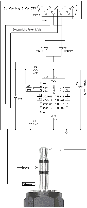
This serial communications circuit uses a minimum number of readily available components. I love designing circuits that are low-cost and work well, so here is my circuit that I designed back in 2000 when a professor friend wanted an interface cable to connect a Casio calculator to the PC. I understand that my circuit is proving to be very popular with students as it is one of the simplest to make.
Efficient use of MAX232 Chip

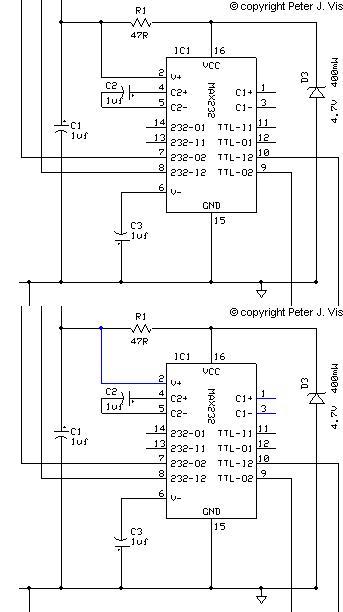
A MAX232 chip normally uses five capacitors, two for the voltage doubler, two for the inverter, and one for the power regulation. However, in this circuit, I am using only three capacitors. This is because I am not using the internal voltage doubler as I already have a voltage source compatible with RS232 levels just after D1 and D2. Hence, pin 2 connects directly to that voltage source, and pin 1 and 3 therefore do not require a capacitor. This is just a little trick I learned from the old days of hacking modems. This method also reduces the power requirements of the chip and increases the chances of it working for almost any PC. A common problem with RS232 communications is that the threshold voltage levels are not always compatible. Hence, by wiring the MAX232 in this way, I am also able to reduce these types of issues.
Powering the Circuit

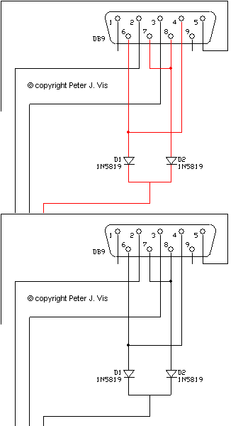
I am taking power directly from the serial port, to power the circuit. It is taken directly from the handshake signals present on the pins that we shall not be using, but happen to be remaining at the positive high level. Diodes D1 and D2 ensure that only the positive voltage gets through.
Zener Voltage Regulator

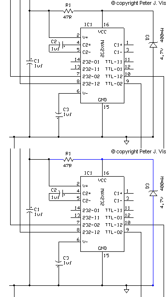
Students often use +5 V regulators, but should really be learning how Zener diodes work to create circuits that are more efficient and low cost. Since the current to drive the circuit is barely enough, I am not using a 7805 in this design, as it is better and cheaper to use a Zener diode D3 with a series resistance R1. For more information about this, please consult the Zener Diode Series Resistor Calculator.
This Article Continues...
Casio Serial CableCasio Cable Circuit
Circuit Power & Serial Port Logic
Casio Cable Circuit Layout
MAX232 Basics for Students
Casio Serial Cable Components
2.5 mm Jack Plug Connection
Casio Serial Cable Circuit Build
Casio Serial Cable Test
Casio Serial Cable Compatibility
Casio Serial Cable Software Configuration